Next: Byte Order Up: Description of the MIPS Previous: Description of the MIPS
The MIPS (and SPIM) central processing unit contains 32 general
purpose 32-bit registers that are numbered 0-31. Register ![]() is designated
by $n. Register $0 always contains the hardwired value
0. MIPS has established a set of conventions as to how registers
should be used. These suggestions are guidelines, which are not
enforced by the hardware. However a program that violates them will
not work properly with other software. Table
is designated
by $n. Register $0 always contains the hardwired value
0. MIPS has established a set of conventions as to how registers
should be used. These suggestions are guidelines, which are not
enforced by the hardware. However a program that violates them will
not work properly with other software. Table ![]() lists the
registers and describes their intended use.
lists the
registers and describes their intended use.
Registers $at (1), $k0 (26), and $k1 (27) are reserved for use by the assembler and operating system.
Registers $a0-$a3 (4-7) are used to pass the first four arguments to routines (remaining arguments are passed on the stack). Registers $v0 and $v1 (2, 3) are used to return values from functions. Registers $t0-$t9 (8-15, 24, 25) are caller-saved registers used for temporary quantities that do not need to be preserved across calls. Registers $s0-$s7 (16-23) are callee-saved registers that hold long-lived values that should be preserved across calls.
Register $sp (29) is the stack pointer, which points to the last location in use on the stack.4 Register $fp (30) is the frame pointer.5 Register $ra (31) is written with the return address for a call by the jal instruction.
Register $gp (28) is a global pointer that points into the middle of a 64K block of memory in the heap that holds constants and global variables. The objects in this heap can be quickly accessed with a single load or store instruction.
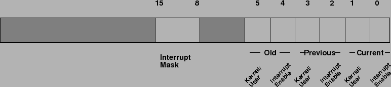
In addition, coprocessor 0 contains registers that are useful to handle exceptions. SPIM does not implement all of these registers, since they are not of much use in a simulator or are part of the memory system, which is not implemented. However, it does provide the following:
| Register Name | Number | Usage |
| BadVAddr | 8 | Memory address at which address exception occurred |
| Status | 12 | Interrupt mask and enable bits |
| Cause | 13 | Exception type and pending interrupt bits |
| EPC | 14 | Address of instruction that caused exception |
Figure
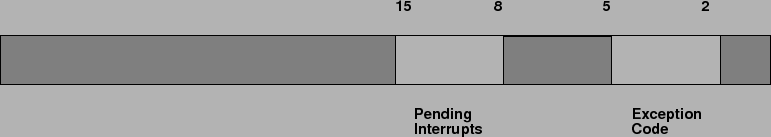
Figure ![]() describes the bits in the Cause
register. The eight pending interrupt bits correspond to the
eight interrupt levels. A bit becomes 1 when an interrupt at its level
has occurred but has not been serviced. The exception code
bits contain a code from the following table describing the cause
of an exception.
describes the bits in the Cause
register. The eight pending interrupt bits correspond to the
eight interrupt levels. A bit becomes 1 when an interrupt at its level
has occurred but has not been serviced. The exception code
bits contain a code from the following table describing the cause
of an exception.
| Number | Name | Description |
| 0 | INT | External interrupt |
| 4 | ADDRL | Address error exception (load or instruction fetch) |
| 5 | ADDRS | Address error exception (store) |
| 6 | IBUS | Bus error on instruction fetch |
| 7 | DBUS | Bus error on data load or store |
| 8 | SYSCALL | Syscall exception |
| 9 | BKPT | Breakpoint exception |
| 10 | RI | Reserved instruction exception |
| 12 | OVF | Arithmetic overflow exception |
Ian Moor 2009-03-11