The idea of using graph colouring for register allocation is covered at the end of Chapter 5 of the lecture notes. However, a good way to understand it is to work through this exercise.
Consider the following sequence of assignments:
        S1:   A = 100;
        P1:
        S2:   B = 200;
        P2:
        S3:   C = A + B;
        P3:
        S4:   D = A * 2;
        P4:
        S5:   E = B * 2;
        P5:
        S6:   F = D - C;
        P6:
        S7:   G = E + F;
        P7:
We are interested in using registers for all the variables in this
code sequence. Notice that we can minimise the number of registers
needed by reusing them.
For example, A and F could both be stored in the same register. We don't need a register for F until after the last statement to use A. There are several such instances in this sequence.
The live range of a variable is the set of program points after which the variable must be safely stored.
Example 1: The live range of A consists of {P1, P2, P3}.
Example 2: The live range of D consists of {P4, P5}
Example 3: The live range of F consists of {P6}.
Subtlety: Can the same register be used for both D and A?
The answer is yes: storage for D is only needed after the value of A has been read. The two live ranges do not intersect.
(as we will see later, A ![]() liveIn(S4), and D
liveIn(S4), and D ![]() liveOut(S4)).
liveOut(S4)).
Two variables interfere if their live ranges overlap.
Example 1: The live ranges of A and F do not overlap.
Example 2: The live ranges of A and B do overlap.
Example 3: The live ranges of A and D do not overlap.
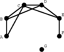
The interference graph for a program consists of
A graph colouring is an assignment of colours to nodes. A graph colouring is valid if no pair of nodes which are linked by an arc carry the same colour.
Construct the interference graph for the variables A, B, C, D, E, F and G in the example program fragment above. Colour the graph using the minimum possible number of colours, and use this colouring to assign each variable to a register. Give the final code after register allocation.
Consider the following program fragment:
        VAR A : ARRAY [0..99] OF INTEGER;

        PROCEDURE P(i, j, size : INTEGER)
        VAR k, tmp : INTEGER;
        BEGIN
          FOR k := 0 TO size-1 DO
            tmp := A[i+k];
            A[i+k] := A[j+k];
            A[j+k] := tmp;
          END
        END
The compiler's intermediate representation of the body of the procedure is as follows:
                t1 := size-1
                k := 0
        L1:
                cmp k,t1
                bgt End
                t2 := Address(A)+i
                t3 := t2+k
                tmp := LoadIndirect(t3)
                t4 := Address(A)+j
                t5 := t4+k
                t6 := LoadIndirect(t5)
                StoreIndirect(t6, t3)
                StoreIndirect(tmp, t5)
                k := k+1
                jmp L1
        End:
 |
 |
|
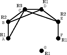
| (a) Interference graph | (b) After colouring |
        S1:   A = 100      R1 = 100
        S2:   B = 200      R2 = 200
        S3:   C = A + B    R3 = R1 + R2
        S4:   D = A * 2    R1 = R1 * 2
        S5:   E = B * 2    R2 = R2 * 2
        S6:   F = D - C    R1 = R1 - R3
        S7:   G = E + F    R1 = R2 + R1
        (i coexists with everything
        j coexists with everything
        k coexists with everything)
        t1 coexists with everything
        t2 coexists with t1 (and i,j,k but asked to ignore them).
        t3 coexists with t1,tmp,t4,t5,t6
        tmp coexists with t1,t3,t4,t5,t6
        t4 coexists with t1,tmp,t3
        t5 coexists with t1,t6,t3,tmp
        t6 coexists with t1,t3,tmp,t5
        R0: t1
        R1: t2, t3
        R2: t4,t5
        R3: t6
        R4: tmp
(you also need registers for i, j and k).
Paul Kelly Imperial College October 2011