|
This is an example of how to transform UML2 Composite Structure Diagrams and Sequence Diagrams to Darwin/FSP.

|
Prerequisites
|
|
Plug-in Check List (see install instructions)
| • | Rational Software Architect 7.0 |
| • | LTSA Eclipse, UML and LTSA-Arch plug-ins installed via Software Updates |
|
|
|
| 1. | Start Rational Software Architect and Create a new UML Project |
| a. | Launch Rational Software Architect |
| b. | Select File à New à Project. |
| c. | In the new project wizard select UML Project and select Next. |
| d. | Provide a project name, e.g. UMLDarwinModel and select Next. |
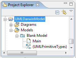
| e. | Under templates keep the default Blank Model and provide a suitable filename, e.g. UMLDarwinModel and click Finish. |
| f. | A new project will be created and selectable in the Project Explorer. |
|
|
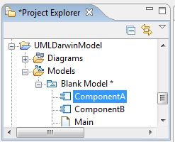
| a. | Expand the Models branch and select the Blank Model |
| b. | Right click the Blank Model branch and select Add UML à Component. |
| c. | Switch to the Properties view and name the component ComponentA under the General sub-tab. |
| d. | Repeat b and c. but create a new component called ComponentB. |
|
|
| 3. | Create the Composite Structure Diagram - Part 1 |
| a. | Right click the Blank Model branch and select Add UML à Collaboration. |
| b. | Right click the new collaboration item Collaboration1 and select Add Diagram à Composite Structure Diagram. |
| c. | Drag and drop both components in to the diagram from the Project Explorer. |
| d. | From the Palette sidebar of the Structure Diagram select the Composite à Port tool. |
| e. | Drop the new port on ComponentA, and select create Class. Name the new class Messenger. Move the new Messenger class to the ComponentA branch in the Project Explorer. |
| f. | From the Palette sidebar of the Structure Diagram select the Composite à Provided Interface tool. Drag and Drop the Provided Interface to the Messenger port and select create new interface. Select the new Provided Interface and rename it Msgs. Move the interface to the Messager class. Right click the interface and select Add UML à Operation and name the operation getMsgs. |
| g. | From the Palette sidebar of the Structure Diagram select the Composite à Port tool. |
| h. | Drop the port on ComponentB, and select create Class. Name the new class MessengerClient. Move the new Messenger class to the ComponentB branch in the Project Explorer. |
| i. | From the Palette sidebar of the Structure Diagram select the Composite à Required Interface tool. Drag and Drop the Required Interface to the MessengerClient port and select select existing element. Enter Msgs and select the ComponentA Msgs interface. |
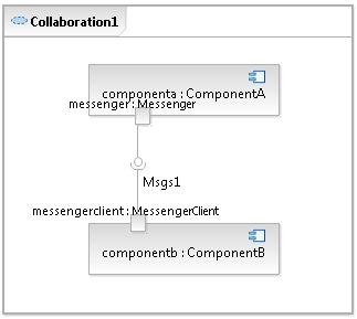
| j. | From the Palette sidebar of the Structure Diagram select the Composite à Connector tool. |
| k. | Select the Messenger port on ComponentA and drag the connector line to the MessageClient port on ComponentB. |
| l. | A new assembly connector between the provided and required interfaces will be shown called Msgs1. |
|
|
| 4. | Create the Composite Structure Diagram - Part 2 |
| a. | From the Palette sidebar of the Structure Diagram select the Composite à Port tool. |
| a. | Drop the new port on ComponentB, and select create Class. Name the new class StatusManager. Move the new StatusManager class to the ComponentB branch in the Project Explorer. |
| b. | From the Palette sidebar of the Structure Diagram select the Composite à Provided Interface tool. Drag and Drop the Provided Interface to the StatusManager port and select create new interface. Select the new Provided Interface and rename it Status. Move the interface to the StatusManager class. Right click the interface and select Add UML à Operation and name the operation getStatus. |
| c. | From the Palette sidebar of the Structure Diagram select the Composite à Port tool. |
| d. | Drop the port on ComponentA, and select create Class. Name the new class Manager. Move the new Manager class to the ComponentA branch in the Project Explorer. |
| e. | From the Palette sidebar of the Structure Diagram select the Composite à Required Interface tool. Drag and Drop the Required Interface to the Manager port and select select existing element. Enter Status and select the ComponentB Status interface. |
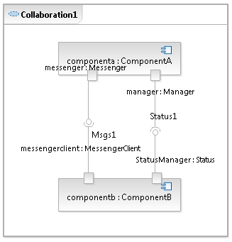
| f. | From the Palette sidebar of the Structure Diagram select the Composite à Connector tool. |
| g. | Select the StatusManager port on ComponentB and drag the connector line to the Manager port on ComponentA. |
| h. | A new assembly connector between the provided and required interfaces will be shown called Status1. |
|
|
| 5. | Add some component behaviour |
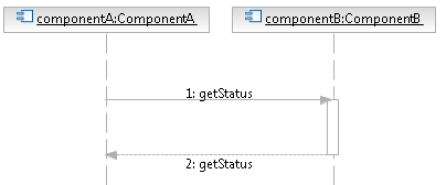
| a. | Select ComponentA in the Project Explorer and right-click to select Add UML à Sequence Diagram. |
| b. | Drag and drop ComponentA and ComponentB in to the diagram. |
| c. | From the Palette sidebar of the Sequence Diagram select the Synchronous Message tool. Select the ComponentA lifeline (under the ComponentA) and drag the message line to ComponentB. In the list of operations, select getStatus(). |
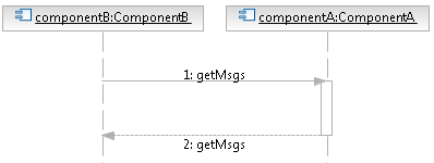
| d. | Repeat a-c but create a new sequence diagram for ComponentB. When adding a new synchronous message, select the getMsgs operation. |
|
|
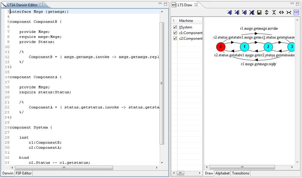
| 6. | Transform the Model to a Darwin Specification |
| a. | Switch to the Navigator View. |
| b. | Expand the project you created in step 1. and select the model name you chose in step 1. |
| c. | Right click the model file and select LTSA-Arch à Darwin |
| d. | A new editor will open with the Darwin specification transformed from the model created previously. |
|
|
|