|

|
Prerequisites
|
|
|
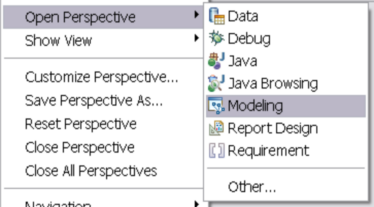
| 1. | Switch to the Modeling Perspective |
| a. | Locate the Eclipse menu bar. |
| b. | Select Window à Open Perspective. |
|
| 1. | Create a new UML Project |
| a. | Select File à New à Project à UML Project and click next. |
| b. | Enter the name of the project as ServiceDeployment and click next. |
| c. | Under Templates select Blank Model. |
| d. | Under Filename enter ServiceDeployment. |
| e. | Under Default Diagram type select Deployment Diagram. |
| f. | Click Finish to create the new project. |
|
| 2. | Import and Apply the Service Deployment Profile |
| a. | Locate the ServiceDeployProfile example profile (or download from the LTSA Samples page). |
| b. | Select File à Import à General à Existing Projects into Workspace and click next. |
| c. | Under Select root directory, browse to the directory containing the root of the ServiceDeployProfile, select the directory and click ok. |
| d. | Ensure the ServiceDeployProfile is checked under Projects: and click Finish. |
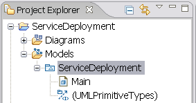
| e. | In the Navigator View, select the ServiceDeployment Project created in Step 1. |
| f. | Under the Models branch in the project, select the ServiceDeployment, right-click and select UML Properties from the pop-up context menu. |
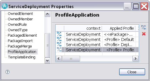
| g. | In the ServiceDeployment Properties dialog, select the ProfileApplication item (on the list to the left). |
| h. | Right-click the ProfileApplication table and select Insert New Profile Application. |
| i. | Select the Profile In Workspace option and browse to the ServiceDeployProfile project imported in a-d. Open the tree and select Profile.epx and click ok and ok again. |
| j. | Select File à Save to update the ServiceDeployment project. |
|
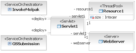
| 3. | Create a Single Servlet Deployment Architecture |
| a. | Under the ServiceDeployment Model, select and open the Main diagram. |
| b. | Now we need to add some objects to this diagram. Locate the Palette toolbar to the right of the main diagram window and select the Node drop-down list and select Stereotyped Node. |
| c. | Place the new Node on the diagram and select Create <<Servlet>> Node. |
| d. | Name the new node object, Servlet1. |
| e. | Now create a new Stereotyped Node, and select its type as <<Server>>. |
| f. | Repeat the process for a new Stereotyped Node of type <<ThreadPool>>. Select the new ThreadPool node and in the Properties view add an attribute named "size" of <Primitive Type> Integer, and Default Value 10. |
| g. | Now add two Stereotyped Artifacts, one for each BPEL orchestration. Select the type as <<ServiceOrchestration>>. |
| h. | Now we need to link the objects. Locate the Palette toolbar to the right of the main diagram window and select the Manifestation drop-down list and select Deploy. Select the first ServiceOrchestration node and link it to the Servlet1 node. Repeat linking the second Service Orchestration node to the Servlet1 node. |
| i. | To link the other objects, select the Association relationship in the Palette and link Servlet1 to the ThreadPool node and Server node. |
| j. | Select File à Save to update the ServiceDeployment project. |
|
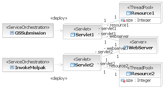
| 4. | Create a Dual Servlet Deployment Architecture |
| a. | Under the ServiceDeployment project, select Models, right-click and select Create New Model. |
| b. | Click next and under filename enter ServiceDeployment2. Click Finish to create a new model. |
| c. | Now repeat step 3. but add two <<Servlet>> and two <<ThreadPool>> stereotyped nodes. |
| d. | Link one orchestration to each Servlet and each Servlet to a ThreadPool. |
| e. | Finally link each Servlet to the one WebServer. |
| a. | Select File à Save to update the ServiceDeployment project. |
|
|
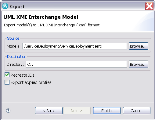
| 5. | Export the Models for use with WS-Engineer |
| a. | Select File à Export and choose Other à UML XMI Interchange Model and click next. |
| b. | Under Source Models browse and select the ServiceDeployment project, and select the ServiceDeployment.emx model. |
| c. | Under Destination Directory select a suitable output folder. |
| d. | Check Recreate IDs and Export applied profiles. |
| e. | Click Finish to export the model in XMI XML format. |
| f. | Repeat a-e for the ServiceDeployment2 model in the same project. |
| g. | Now both of these exported models can be used as input to the Deployment Checking example in Tutorial 1. |
|
|