Aim
Design and build a set of calipers to measure the length of items, you will need to:
- Move to a fixed position - fully open.
- Slowly close the jaws, using an optical encoder to measure the distance travelled.
- Since the LEGO optical sensor is reflective, you will have to determine its focal length - the optimal distance to place the encoder - by experimentation (unless you find it documented somewhere).
- Stop when the object to be measured is engaged
- Display the calculated length of the item on the RCX's LCD panel.
Notes / Comments
Design One
We began with the idea of driving a rod with spaced saw-tooth blocks through a ridge to push against the object to be measured, which would be supported at the back by a set of stationary blocks. By gearing the motor down for driving the rod, we could achieve a slow, steady but powerful movement to overcome any friction of it sliding through the ridge, and we could gear up for the shaft encoder, increasing the ratio of turns of the shaft encoder wheel to the distance moved by the rod, giving us increased accuracy. However, we found that we only had two saw-tooth blocks available, which would require too many cogs to drive a 30cm rod.
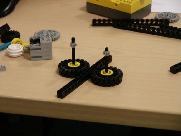
Design Two
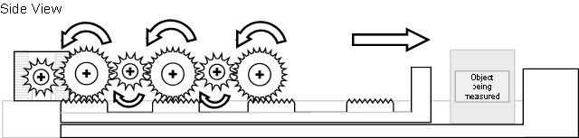
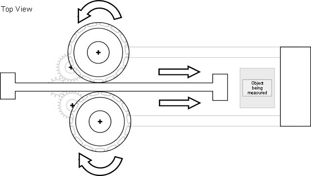
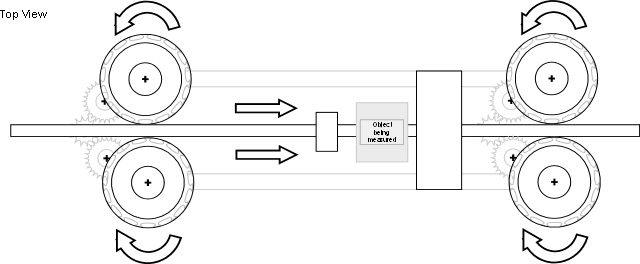
Our second idea was to drive the rod through two wheels rotating in opposition to one another. The wheels would be fitted with rubber tyres and place close enough together that friction between the wheels and the rod would be enough to drive it through the ridge. Again, we could gear down the wheels for extra power and gear up the shaft encoder wheel for accuracy. Since this system merely relied on friction between the wheels and the rod, and not on saw-tooth blocks, the maximum size measurable was only restricted by the length of the rod (and the support structure, if any). This swayed us to choosing this design to be implemented.
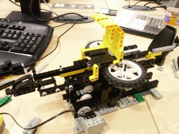
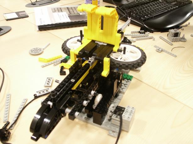
Initial implementation
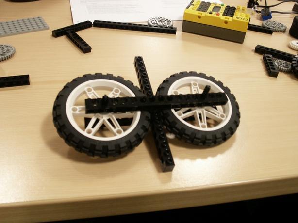
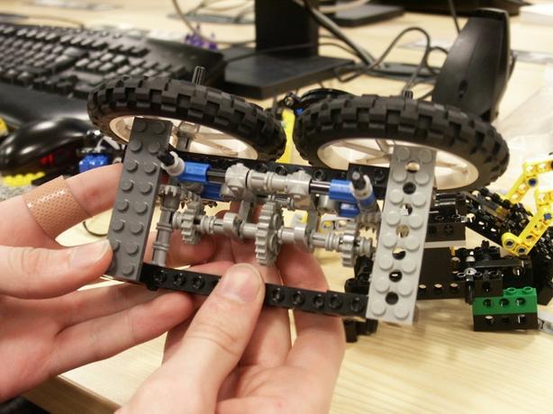
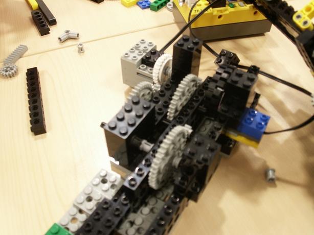
We decided to have the two wheels push the rod through a horizontal channel, which posed the initial problem of powering the two wheels (whose rods were now pointing vertically). To avoid mounting the motors vertically, we implemented a set of gears to convert the motion from a vertical rotation to a horizontal rotation. We then implemented the base, which housed three levels of small-to-large cogs in order to gear down the motor enough so that it would be strong enough to push the rod through the wheels. Finally, we had one level of large-to-small cogs to gear up again for the shaft encoder wheel. This would cause the shaft encoder wheel to turn faster relative to the driving wheels, providing greater accuracy.
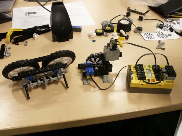
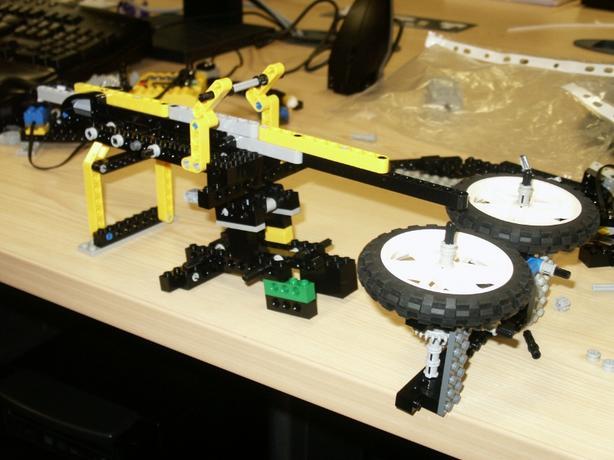
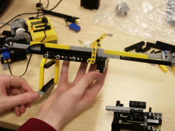
Finally, we implemented the channel through which the rod would be driven. This supported the rod underneath and at the sides for the measurable distance, and also above prior to going through the wheels. We needed the rod to be held fairly tight in the channel, in order to direct it as it was being driven through the wheels (due to the single driving point).
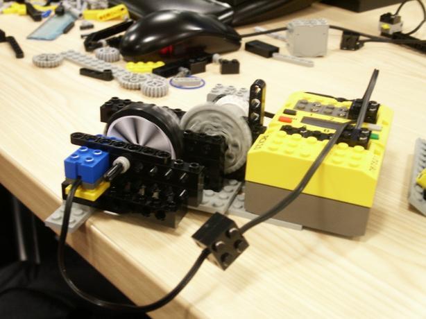
For the shaft encoder, we attached the shaft encoder disk to a large cog and positioned the light sensor 4.5 millimeters from it, which we found to be the optimal distance for focusing the light on the disk. We chose the shaft encoder disk with the largest spacing between segments, since this would decrease the chances of us missing a colour change and we had already planned for high accuracy by turning the shaft encoder disk faster compared to the driven measuring rod.
Detecting collision
Our robot had to be capable of detecting when it had collided with the object being measured in order to display the size of the object and stop driving the rod. We decided to do this by positioning a slip gear in our gearing system that would prevent the gears from moving when a certain force was reached. By placing the shaft encoder after the slip gear, it would stop detecting motion when a force is exerted against the rod. This would allow us to detect a collision by placing a timeout on the colour change of the shaft encoder.
Results
| Object | Real Size | Measured Size |
|---|---|---|
| 2x2 Lego Block | 16mm | 10mm |
| 2x4 Lego Block | 32mm | 23mm |
| Small Lego Wheel | 30mm | 28mm |
| Medium Lego Wheel | 50mm (ish) | 41mm (ish) |
| Large Lego Wheel | 84mm | 80mm |
| Calculator | 165mm | 152mm |
| Torch Lego Block | 145mm | 129mm |
| 16 x 1 Lego Block | 128mm | 112mm |
| Computer Mouse | 115mm | 93mm |
Problems
We encountered a number of problems with our design, which we attempted to overcome. Firstly, we realised that the channel through which we were driving the rod had to be open on one side, so that the calipers on the end of the rod would slide through. This caused a problem because the forces on the wheels caused them to move about, driving the rod out of the channel. To reduce this problem, we decided to make the open side of the channel the top, so that gravity would help hold the rod in place, and also cover the channel at the rear section, before the rod goes through the wheels, to help line it up properly.
The second problem we encountered was deciding where to place the slip gear in our gearing system. We found that if we placed it at the motor end, before we geared down to turn the wheels, then there wasn't enough force generated when the rod hit the object to cause it to slip. Conversely, placing it after we geared down to drive the wheels meant that it required to little force to slip, and would slip when merely driving the rod through the system. In the end, we altered our gearing system such that we didn't gear down the wheels as much, and positioned the slip gear in the middle, after one large-to-small downshift but before the other. This meant that the force of pushing the rod through the system wasn't quite large enough to cause it to slip, but if there was resistance to the rod's movement then the force would increase past its threshold.
Improvements
The main problem with our design was ensuring that the rod remained in the channel as it was driven through by the wheels, and this was due to the single driving point. One solution to this problem would be to replicate the wheel structure on the other side of the measuring block, so that the rod would be driven in two points. Also, if we position the wheels vertically as opposed to horizontally, then gravity would have helped add to the friction between them and the rod making it much better.
We also found that the large wheels used to drive the rod amplified problems caused by slack in the large number of gears between the motor and the wheels, generating a jerky movement rather than a smooth one. By using smaller wheels and attempting to reduce the number of gears in our gearing system, we could achieve a smoother movement and greater measuring accuracy.