Aim
Design and build a mobile robot that can follow a continuous black line on a white surface using one/two optical sensors. There are several possible drive and steering combinations that you might consider.
Physical Designs
During the course of this exercise, we considered several physical designs for our Robot, and implemented various things. The main considerations were the placement and possible movement of the light sensor(s) for detecting the line, the gearing and size of our wheels/motor and the method of balancing the robot at the back. We also 'borrowed' the design of our collision detector, as will be discussed.
Flexible Light Sensor Positioning
As described with the source code for this exercise, we considered the idea of having a flexible front gantry that could rotate as the code dictates, so that an attached light sensor or two would alway be in the correct position relative to the line. The robot would then drive forward and its turning would be provided by wheels rotated with the front gantry, allowing for greater velocity.
While this would have been a great thing (and indeed at least one other group managed to implement this), at the start of the coursework, we felt it to be a very high-risk approach as there are many issues that need resolving. Firstly the turning circle needs to be small enough so that the robot can easily track the line, but not require the wheels to move so far as to end up positioning them at 90 degrees to the drive wheels.
Secondly, there is 'ackerman effect' which may have needed to be compensated for. If the wheels are rotated to induce turning, unless the inner wheel is rotated by a greater amount than the outer one, there is an undue force applied to the wheels and/or the turning mechanism. Also there will be no defined turning circle center, which could make calibration for 'how much to turn left/right' difficult.
A solution to this problem could be to use a single wheel on the turning gantry, but this could induce new problems of stability, especially around sharper corners (and it is likely that any such gantry will be top heavy owing to a motor to be able to turn it and the wheel, moving the center of gravity up and influencing stability further).
Static Light Sensor Positioning
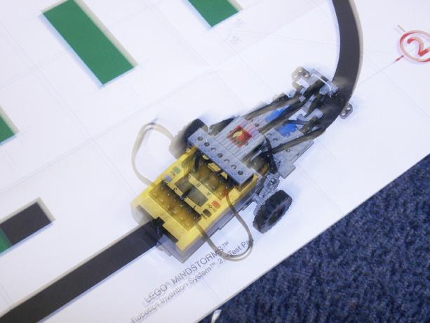
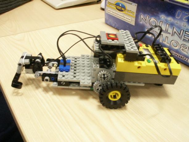
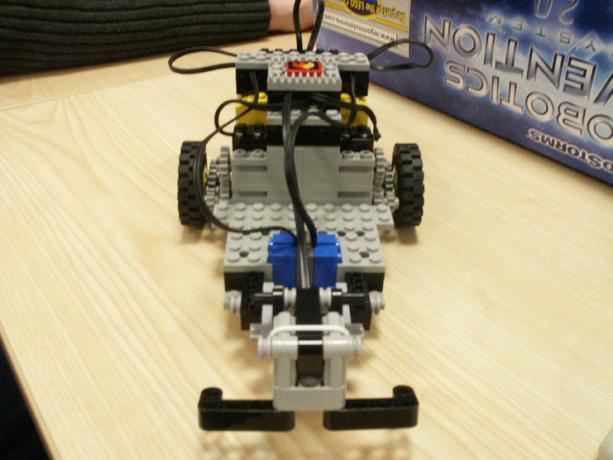
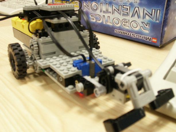
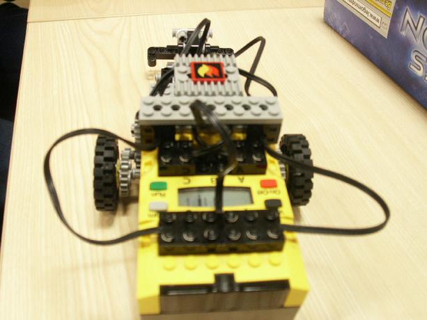
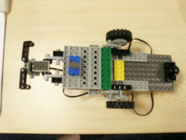
Static light sensor positioning. Here we attached the light sensor(s) to the 1-piece robot. Because we were not using a rotational-steering based mechanism (and had instead opted for differential drive), we knew it was most important to move the light sensors as far from the turning center as possible. The makes it much easier to determine which side the line has been entered/exited from in a two-sensor configuration, and also allows for lots of smaller adjustments at the motors to keep the robot on the line and moving in a smooth manner.
Motors and Drive
As already mentioned, we opted away from a rotation-steering based robot and instead concentrated on a differential drive one. This required two motors being mounted towards the rear of the robot, and allowed for our robot to achieve 0-turning cicle turns in parts of the assessed track.
Wheel Gearing and Size
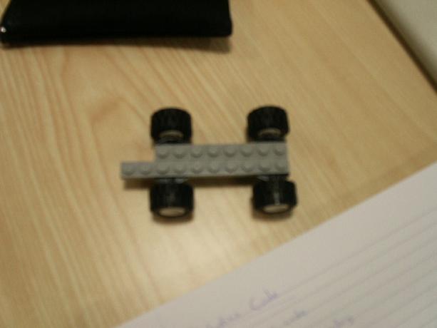
We found that the robot travelled very fast initially, and it was difficult to steer it to stay on the black line without it snaking back and forth across it (and possibly loosing the line on corners). To combat this we slowed the robot down. However to do this in software was not satisfactory (lowering the voltage on the motors lowers overall energy in the system, wheras we wanted to trade speed off against torque to maintain control of the robot). We achieved this by gearing down the wheels of the robot once to achieve the desired velocity and controllability of the robot.
Robot Balance
For the differential drive, we had two wheels directly connected to two motors (via a small gearing mechanism). However we needed at least a 3rd point of contact to maintain the stability of the robot. As our design was using the RCX brick as the 'back' of the robot, and a light-weight construction for the front, it made sense to place this third point of contact at the back and so contain the center of gravity for stability. Because we wanted to maintain a 0-turning cicle, and not have the effects of steer that a castor would have brought, we opted instead for a smooth suppot which would skid on the paper track. Although this induces some friction, the choice of a rounded smooth block makes this negligable, and the no-oversteer we get compared to a castor more than compensates for this fact.
Bump Sensor
As part of the assessed exercise, we were required to detect 'bumping' into something. For simplicity, and effectivness, we reused the design of bump sensor provided in the 'Mindstorms' manual, adjusing its connection interface and front contacts slightly for our purposes. This proved a very effective simple design that caused no hassle or problems during usage.