
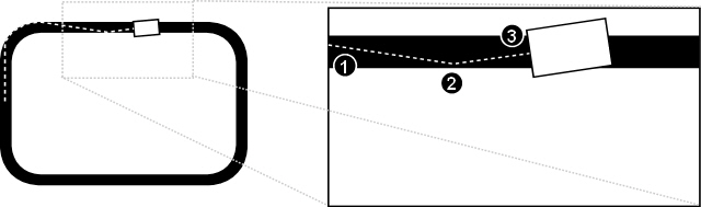
Aim
Design and build a mobile robot that can follow a continuous black line on a white surface using one/two optical sensors. There are several possible drive and steering combinations that you might consider.
Coding Designs
As well as coming up with different designs for our robot, we also considered how we would code the control system for each design, weighing up the complexity of the code and how likely it was to work when we decided which design to implement. Here we detail some of the designs we considered.
Single, Fixed Light Sensor
Our simplest robot design consisted of a single light sensor fixed to the front of the robot. The single light sensor would be able to detect the change of brightness between the white background and the black line and, using this, the control system could work out whether or not the robot was over the line. However, this requires extra complexity from the robot's behaviour, since if the robot was to wander off the line we would not be able to determine from this single reading on which side of the line it had left.
The first solution to this was to use the fact that the circuit is a loop and that the robot starts inside it. With this, we could implement a system whereby the robot stays contained within the loop, never crossing the line. We did this by adapting a standard wall-following algorithm, such that when the robot hits the line, it rotates on the spot until pointing away from it, then arcs (rotating and moving forwards) until it hits the line again. Since the robot never crosses the line, we know that if it always arcs in the same direction then it will stay within the loop and slowly follow the line around the circuit.
- 1) The light sensor detects the line. The robot turns right for a predetermined amount of time. Ideally, this turn should be done on the spot, so a differential drive mechanism is preferred.
- 2) The robot moves forward and turns left, arcing towards the line.
- 3) The light sensor detects the line again, and the process repeats.
We translated this behaviour into NQC-like pseudocode to see how complex it would be to implement.
task main() {

  initialise(); 	// Set up motors and sensor
  calibrate(); 	// Calibrate the light sensor

  // For now we assume that we're near the line,
  // later a separate behaviour will find the line
  // and move the robot onto it
// We've detected the line, so turn right
      SetPower(LEFT_MOTOR+RIGHT_MOTOR, FULL_POWER);
      OnFwd(LEFT_MOTOR);
      OnRev(RIGHT_MOTOR);

      // By adjusting this wait time, we can vary how far
      // we turn, and so how large the arcs are
      Wait(50);

      // Move forward a bit so we don't immediately detect
      // the line again
// We don't detect the line, so arc left
      SetPower(LEFT_MOTOR, HALF_POWER);
      SetPower(RIGHT_MOTOR, FULL_POWER);
      OnFwd(LEFT_MOTOR+RIGHT_MOTOR);

  }

}
The main problem with this method is that it doesn't attempt to stay within the line, but instead keeps to one side of it. By reducing the amount the robot turns when it detects the line, we can decrease the size of the arcs and make the robot follow the line more closely. However, because the robot is constantly stopping and turning, this process will be very slow.
An improvement would be to first find the line, then move forward while detecting the line and rotate on the spot when the line is not detected. This would keep the robot moving inside the width of the line.
- 1) The light sensor stops detecting the line. The robot turns left for a short, predetermined amount of time.
- 2) Now detecting the line, the robot moves forward and turns right, arcing towards the edge of the line.
- 3) The light sensor stops detecting the line again, and the process repeats.
task main() {

  initialise(); 	// Set up motors and sensor
  calibrate(); 	// Calibrate the light sensor

  // For now, we assume we're on the line - later a
  // separate behaviour will find the line and turn
  // the robot onto it
// We've stopped detecting the line, so turn left
      SetPower(LEFT_MOTOR, FULL_POWER);
      SetPower(RIGHT_MOTOR, FULL_POWER);
      OnRev(LEFT_MOTOR);
      OnFwd(RIGHT_MOTOR);

      // By adjusting this wait time, we can vary how far
      // we turn, and so how large the arcs are (this needs
      // to be quite small to stay within the width of the
      // line)
      Wait(20);

      // Move back into the centre of the line again
// We detect the line, so arc right
      SetPower(RIGHT_MOTOR, HALF_POWER);
      SetPower(LEFT_MOTOR, FULL_POWER);
      OnFwd(LEFT_MOTOR+RIGHT_MOTOR);

  }

}
Although this will keep the robot within the line, the need for it to stay within the line's width means that the arcs must be very small, making this potentially much slower than the first solution.
Single, Moving Light Sensor
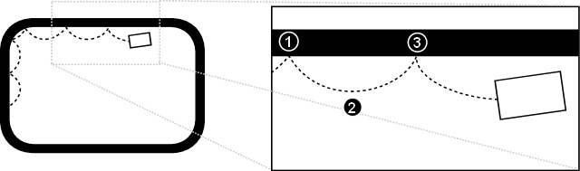
To keep the robot within the line and prevent it from having to stop and turn all the time, we considered placing the light sensor on a gantry attached to a motor which could rotate it in front of the robot. The arc of the gantry would be greater than the width of the line, such that as the gantry rotates from one side of the robot to the other the light sensor would cross the line if the robot is parallel with it.
By constantly rotating the gantry and sampling the light sensor reading when it reaches each extreme, we should receive two white readings when the robot is on and parallel with the line, but when the robot moves away from the line we should get a black reading at one of the extremes. At this point, we can turn towards that side for a predetermined amount of time so that the robot is parallel to the line again.
- 1) The robot is on and parallel (ish) with the line, so we get two white readings (on different sides of the line) when the light sensor is at each extreme of the gantry's rotation.
- 2) The robot is beginning to move off the line, so when the light sensor is at the right extreme of the gantry's rotation it gives a black value. So, the robot stops and turns right on the spot for a predetermined amount of time, then continues forward.
- 3) After moving forward for a while, we detect that the robot is moving away from the line again, so turn right again and repeat the process.
task main() {

  initialise(); 	// Set up motors and sensor
  calibrate(); 	// Calibrate the light sensor

  // For now, we assume we're on the line - later a
  // separate behaviour will find the line and turn
  // the robot onto it

  // We use left and right touch sensors to detect
  // when the gantry reaches the left and right
  // extremes of its arc
// Move the gantry to the left extreme (we'll say
    // that driving the gantry motor rotates the gantry
    // left)
    OnFwd(GANTRY_MOTOR);

  }

  // Keep track of whether the gantry is moving left
  // to right or vice versa
// Take a sample for one extreme
// Wait until the gantry reaches the other extreme
// Take a sample at the other extreme
// If we detected black on the left, turn
        // left
// If we detected black on the right, turn
        // right
// If we detected black on the right, turn
        // right
// If we detected black on the left, turn
        // left
// Swap the state, since the gantry will now
    // move in the opposite direction
    state = !state;

  }

}
This method smooths out the jagged movement produced by the fixed light sensor method because the robot doesn't stop and turn until it has deviated from the line by a certain amount. However, the robot still has to stop and turn on the spot, and this method essentially reproduces the effect of two light sensors since we only take two samples.
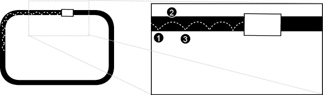
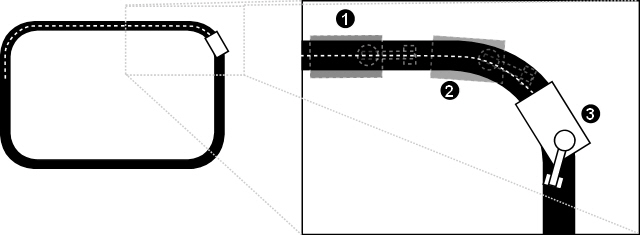
Our final one-sensor behaviour was to continually sample the light sensor value as the gantry rotates and the sensor sweeps across the line. By recording how long the sensor spends to the left and to the right of the line as it sweeps across, we can determine the robot's current angle relative to the line and correct it.
When the gantry is at one extreme, we initialise two variables (countOne and countTwo) to zero, then begin sampling. We store the number of white readings before the first black reading in the countOne variable (if our first reading is black then we set this to zero). We then ignore black readings (readings taken while the sensor crosses the line) until the first white reading, and begin recording the number of white readings in countTwo.
Assuming that we sample the light sensor at consistent intervals, countOne and countTwo will contain a representation of the amount of time the light sensor spent on each side of the line. If the gantry was sweeping from left to right, we take the different between countOne (the amount of time spent to the left of the line) and countTwo (the amount of time spent to the right of the line), then add this difference to the power of the left motor and subtract it from the power of the right motor. If the difference is positive, it means the sensor was to the left of the line for longer than the right, so we increase the power of the left motor and decrease the power of the right to turn it to the right. If the difference is negative, we do the opposite to turn to the left. Since the gantry sweeps in both directions, we have to negate the figures when sweeping right to left.
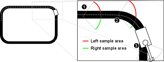
- 1) The robot is parallel to the line, so the number of samples taken on the left of the line (in red) is roughly equal to the number of samples taken on the right (in green). The difference will therefore be zero so both motors will drive forward at equal power and the robot will move in a straight line.
- 2) When the robot begins to move off to the left of the line, more samples will be taken on the left of the line than on the right. The difference will therefore be positive, so the left motor will gain power and the right motor will lose power, causing the robot to turn to the right.
- 3) This process continues until the robot is parallel with the line again
task main() {

  initialise(); 	// Set up motors and sensor
  calibrate(); 	// Calibrate the light sensor

  // For now, we assume we're on the line - later a
  // separate behaviour will find the line and turn
  // the robot onto it

  // We use left and right touch sensors to detect
  // when the gantry reaches the left and right
  // extremes of its arc
// Move the gantry to the left extreme (we'll say
    // that driving the gantry motor rotates the gantry
    // left)
    OnFwd(GANTRY_MOTOR);

  }

  // Keep track of whether the gantry is moving left
  // to right or vice versa
// Set the motors going forward (we'll only vary
  // their power)
// Initialise variables for storing the number of
    // white samples taken on each side of the line
// Sweep the gantry until the line is detected or
    // it reaches the other extreme
// As long as the line hasn't been detected,
      // keep counting samples on this side
      countOne++;

    }

    // Sweep the gantry until the line has been crossed
    // or it reaches the other extreme
// Sweep the gantry until it reaches the other extreme
// As long as the extreme hasn't been reached,
      // keep counting samples on this side
This method produces a rough estimate of the angle between the robot's current path and the line, varies the power to each motor based upon this value, providing a Braitenberg-like behaviour. This has the big advantage that the amount the robot turns is related to the amount it needs to turn to align itself with the line, so the robot should perform smooth movements without stopping and starting as in previous designs. One potential problem with this design is with the speed of the gantry and the accuracy of the light sensor while it is moving. Ideally, we want the gantry to move fast, so it quickly completes its sweeps and updates the motor powers at regular, short intervals to provide a smooth movement. However, the light sensor reading may be inaccurate if the sensor is moving quickly across the line, and any delay between the reading being taken and reported would cause a bias against the direction in which the gantry is rotating.
Dual, Fixed Light Sensors
Two light fixed light sensors provide an advantage over one in that they can be used to determine on which side the robot has left the line without having to be moved. This means there is no need for the robot to continually arc. Once on the line it merely has to move in a straight line until it detects that it has left the line on one side, then turn towards the opposite side. This simplifies the control system a fair bit.
- 1) Both light sensors detect the line, so the robot moves forward.
- 2) The right light sensor detects white while the left light sensor detects black, so the robot stops and turns to the left.
- 3) Both light sensors detect the line again, so the robot continues as before and the process repeats.
task main() {

  initialise(); 	// Set up motors and sensor
  calibrate(); 	// Calibrate the light sensor

  // For now, we assume we're on the line - later a
  // separate behaviour will find the line and turn
  // the robot onto it
// Record in two variables whether the line is
    // detected by either light sensor
// Both sensors detect the line, so move forwards
// We only detect the line on the left, so turn
      // towards it
// We only detect the line on the right, so turn
      // towards it
      OnFwd(LEFT_MOTOR);
      OnRev(RIGHT_MOTOR);

    }

  }

}
This system will ensure that the robot keeps within the line, but still causes a fair amount of snaking from one edge of the line to the other, since the robot may not be perfectly parallel after it leaves a bend.
To smooth out the robot's movement, we want to change its behaviour so that it turns only a small amount to correct its heading when travelling along the straights, but turns a large amount when it reaches a bend. However, when we go off the line, we have no way of determining whether we've reached a bend or have simply drifted off of a straight. One thing we can do, though, is to start turning a little when the robot initially leaves the line, then gradually increase the sharpness of our turning until the line is found. Since a small turn is all that's needed to correct the robot's movement along a straight, it will re-enter the line at a more acute angle than if we performed a sharp turn, and therefore will not deviate from the line as much. On the bends, the robot will start turning slowly but, because small turns aren't enough for it to reach the line, will turn sharper until it makes it way around the bend.
To implement this, we just need to vary the power to each motor based on the amount of time one light sensor spends off the line. We used two variables, leftPower and rightPower, to represent the power of the left and right motors respectively, and just subtracted a value from this every time we go through the loop while one sensor is off the line.
task main() {

  initialise(); 	// Set up motors and sensor
  calibrate(); 	// Calibrate the light sensor

  // For now, we assume we're on the line - later a
  // separate behaviour will find the line and turn
  // the robot onto it

  // Initialise our variables for tracking the power
  // of each motor
// Set both motors moving forwards - we're only
  // going to vary their power in the loop
// Record in two variables whether the line is
    // detected by either light sensor
// Both sensors detect the line, so set both motors
      // to full power to move forwards
// Only the left sensor detects the line, so gradually
      // decrease the power of the left motor to cause a
      // smooth turn in that direction
// Only the right sensor detects the line, so gradually
      // decrease the power of the right motor to cause a
      // smooth turn in that direction
      leftPower = FULL_POWER;
      rightPower -= 1;

    }

    SetPower(LEFT_MOTOR, leftPower);
    SetPower(RIGHT_MOTOR, rightPower);

  }

}
Dual, Moving Light Sensors
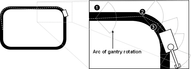
Whereas before, with a single light sensor, we had to continually sweep the line in order to work out the angle between the robot's direction and the line, now we can simply keep our gantry inside the line and use this to lead the robot in the correct direction. Unlike the previous designs which use differential drive, this method is more suited to Ackerman steering, since the angle of the gantry relative to the robot can be directly tied to the angle of the steering wheel.
- 1) Both light sensors detect the line, so the gantry stays where it is and the steering wheel points forwards, so the robot moves forwards in a straight line.
- 2) The left light sensor moves off the line, so the gantry is rotated right until both sensors are back on the line. This has the effect of also rotating the steering wheel, so the robot starts turning right.
- 3) Further around the bend, the gantry starts moving off the inside of the line. Here the right light sensor detects that it is off the line, so the gantry is rotated back towards its central position. This has the effect of realigning the steering wheel to point forward once the bend has been taken.
task main() {

  initialise(); 	// Set up motors and sensor
  calibrate(); 	// Calibrate the light sensor

  // For now, we assume we're on the line - later a
  // separate behaviour will find the line and turn
  // the robot onto it

  // We're using Ackerman steering, so both driving motors
  // can constantly move forward [if we had a clever gearing
  // system, we may only have one motor to do this, and
  // avoid differential drift...]
// Record in two variables whether the line is
    // detected by either light sensor
// We only detect the line on the left, so drive the
      // gantry motor to turn the gantry in that direction,
      // which will also turn the steering wheel in that
      // direction since it is directly connected to the
      // gantry
// We only detect the line on the right, so drive the
      // gantry motor to turn the gantry in that direction,
      // which will also turn the steering wheel...etc.
      OnRev(GANTRY_MOTOR);

    }

  }

}
Using this system, the robot will not snake on the straights, since the gantry adjusts the Ackerman steering to ensure smooth corrections to the robot's heading until it is parallel with the line. The only problem with this system is that the robot can overshoot the bends if the gantry does not move fast enough to track the line as it curves. This can be improved by extending the length of the gantry, so that it has to rotate less as it reaches a bend.
Our Design
For our design, we decided to go for dual light sensors in a fixed position, since this struck a balance between simple code and accuracy. We decided not to use the system with moving light sensors since one of the goals of the exercise is to perform an 180-degree spin, which is difficult to achieve using Ackerman steering. By using our method described above to smooth the turning of a differential drive robot, we were confident that we could achieve close, smooth following of the line with fixed light sensors.
Having decided on our robot design and line following code, we needed to implement the other behaviours that would initially find the line and also rotate the robot when it hit the obstacle for the first time. We moved the line following code into a separate tasks and implemented three new tasks. The monitorLight task continually checks the values of the light sensors and stores their state (either STATUS_WHITE or STATUS_BLACK) in two global variables (statusLeft and statusRight) that is then be read by all the other tasks. The findLine task moves the robot forwards until one of the light sensors detects the line, then it rotates the robot left for a predetermined amount of time to initially line it up with the line. Finally, avoidObstacle monitors the front bump sensor and, when it detects pressure, causes the robot to stop, reverse a small amount and then rotate left for a predetermined amount of time. A global state variable determines which stage of the course the robot is currently in and hence which tasks are active, and an arbiter task determines command precedence and performs the actual motor control.
Sensor Calibration
As in the first assignment, we needed to calibrate our light sensors to determine what values they produce on the white background and on the black line. When the control program starts, it enters a loop that continually samples both light sensors and records the maximum and minimum values for each. When the bump sensor is pressed, this loop exits and the threshold value for each light sensor is calculated as half the difference between the maximum and minimum values. By moving the robot over the black and white colours before pressing the bump sensor, the robot will record the lowest light reading as black and the highest as white. The threshold value will cause a change in state (whether the line is detected or not detected) whenever a light sensor value crosses the value half way between the calibrated black and white values.
Problems
The main problem we had was getting the smooth line following to work. Initially, we implemented the jerky line following where every turn required the robot to stop and then drive one motor forward and one in reverse. This followed the line fairly well, but was slow and would sometimes over-compensate and produce a large amount of snaking along the straights. We improved upon this by adding a float-turn, where one motor would float rather than reverse, so the robot didn't have to come to a complete halt every time. However, when we came to implementing our power-varying method described above, we encountered a number of problems.
The first problem was that our initial implementation of decreasing the power to one of the motors linearly over time did not cause the power to decrease fast enough to avoid the robot overshooting the line at the bends. We tried fixing this by adding a delta value that we could increment, causing an increasingly larger value to be subtracted from the power each time through the loop (so that the power decreased quadratically). Again, we found this still not to be fast enough, so we tried doubling the delta each time (providing an exponential power decrease). This highlighted another problem, which was that the motors would not show a significant speed difference at high powers. This was conflicting with our quadratic and exponential decreases, since they would initially vary the high power by very small amounts, causing no noticeable speed decrease, before then shooting through the low powers very quickly, causing a sudden decrease that was equivalent to a motor float. In the end, we didn't have time to find good values for achieving smooth movement, so we had to abandon this approach.