| a. | In Project Explorer, select the ModeModel model (e.g. Automotive) and right-click to show the context pop-up menu. |
| b. | Select Add UML à Package. A new package branch will be added to the ModeModel in the Project Explorer view. |
| c. | Rename the new package Convoy. |
| d. | Switch to the Stereotypes perspective of the model properties. |
| e. | Select Apply Stereotypes select the Mode from the ModesProfile profile and click OK. |
| f. | Note that the stereotype is added to the applied stereotypes list. |
2. Add a Mode Collaboration
| a. | In Project Explorer, select the Mode Convoy and right-click to show the context pop-up menu. |
| b. | Select Add UML à Collaboration. A new collaboration branch will be added to the Convoy Mode in the Project Explorer view. |
| c. | Rename the new package ConvoyCollaboration. |
| d. | Switch to the Stereotypes perspective of the model properties. |
| e. | Select Apply Stereotypes select the ModeCollaboration from the ModesProfile profile and click OK. |
| f. | Note that the stereotype is added to the applied stereotypes list. |
| g. | In Project Explorer, select the ModeCollaboration ConvoyCollaboration and right-click to show the context pop-up menu. |
| h. | Select Add Diagram à Composite Structure Diagram. A new component diagram branch will be added to the ConvoyCollaboration node in the Project Explorer view. |
| i. | Rename the new package ConvoyComposite. |
3. Import some Components
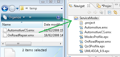
| a. | Switch to the Navigator view |
| b. | From Windows Explorer, locate the Automotive Case Study files and drag-and-drop them on to the ServiceModes project folder in the Navigator view (as shown below) |
| c. | Switch to the Project Explorer view |
| d. | Open the OnRoadAssistance model and navigate to the Vehicle package. |
| e. | Select GPS, LocalDiscovery, Orchestrator, Reasoner and Vehicle Communication Gateway components, right-click and select Copy. |
| f. | Navigate back to the Mode Convoy package and right-click and select Paste. |
| g. | Then back in the OnRoadAssistance model, navigate to the VehicleExternal package and select the RemoteDiscovery component. |
| h. | Copy and paste the RemoteDiscovery component in the Mode Convoy package. |
| i. | Now select the Mode Convoy package, and right-click and select Add UML à Component. Name the new component OtherVehicle. |
| j. | For each component we need to add stereotypes for their service role. We add this by selecting each component, and in the Properties view adding a stereotype based upon their role. To add a keyword stereotype, select the component, select Stereotypes and enter the stereotype in the keywords text box. |
| k. | Stereotype the components added as follows: |
GPS
|
provider
|
LocalDiscovery
|
requester, provider
|
Orchestrator
|
requester, provider
|
Reasoner
|
requester, provider
|
Vehicle Communication Gateway
|
requester, provider
|
RemoteDiscovery
|
requester, provider
|
OtherVehicle
|
provider
|
| l. | Drag and drop each component on to the ConvoyComposite diagram editor. |
| m. | Note now you have some new properties of the ConvoyComposite (for each component added) as shown below. |
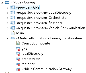
| n. | For visual clarity, add the same stereotypes to each component property. |
3. Linking Required and Provided Services
| a. | On the ConvoyComposite diagram locate the Palette sidebar and under Composite Structure drop the list for Provided Interface to select a Required Interface. |
| b. | Then move over to the LocalDiscovery component and locate the Port <<service>> localDiscoverServices. Drop the Required Interface on this port. |
| c. | When prompted, choose Select Existing Element and type Location in select an element text box. Choose the «serviceInterface» Location - Automotive::Convoy::GPS::Location element. |
| d. | Now go back to the Palette sidebar and select Connector. Move back to the LocalDiscovery component and click the port then whilst holding down the left mouse button (to drag the connecting line) move down to the GPS component and release the connector on the visible port. This binds the two interfaces together. Name the connector GPSBinding. |
| e. | Now proceed to add Ports, Required and Provided Interfaces to the rest of the Composite Structure as listed in the table below. |
From Service
|
To Service
|
To Provided Interface (new = new port)
|
Connector Name
|
Orchestrator
|
LocalDiscoveryService
|
findLocal (new)
|
localBind
|
Orchestrator
|
Reasoner
|
ServiceSelection
|
reasonserBind
|
Orchestrator
|
Vehicle Communication Gateway
|
AccessExtServices (new)
|
vcgBind
|
Vehicle Communication Gateway
|
RemoteDiscovery
|
RemoteServices
|
remoteBind
|
RemoteDiscovery
|
OtherVehicle
|
VCG (new)
|
vcgBinding
|
4. Create other Mode Packages for "Detour" and "Planning"
| a. | Now repeat steps 1-3 but create one Mode Package for a "Detour" mode composition and one for "Planning". |
| b. | The differences in each package are as follows: |
| c. | For the Detour package, replace the OtherVehicle component with a new "HWEmergency" component. Add suitable ports, interfaces and bindings between the Vehicle Communication Gateway and the HWEmergency component. |
| d. | For the Planning package, replace the OtherVehicle component with a new "RoutePlanner" component. Add suitable ports, interfaces and bindings between the Vehicle Communication Gateway and the RoutePlanner component. |
|